In-situ Concrete for roof decks shall be specified and produced in accordance with BS EN 206:2013 and installed in accordance with BS13670:2009 and the National Structural Concrete Specification.
Normal Weight and Lightweight concretes are suitable substrates for most IKO Waterproofing system applications.
As defined in BS EN 206:2013, Normal Weight and Lightweight concrete shall have a density of 2000kg/m3 – 2600kg/m3 and 800kg/m3 – 2000kg/m3 respectively.
Concrete finish
The concrete roof deck shall be finished with either a Basic or Ordinary Finish which are achieved with a Skip Float (Easy Float) or Power Float as appropriate.
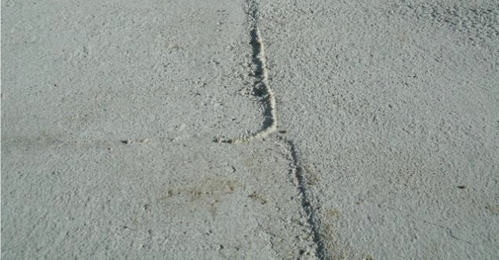
Figure 1 – typical raised float ridge
Decks suitable to receive the waterproofing system should be free from raised float marks or protruding aggregate which will cause potential thinning of any liquid coating/primer or lack of adhesion of the waterproofing system. Such blemishes will need to be ground flat prior to installing the waterproofing system.
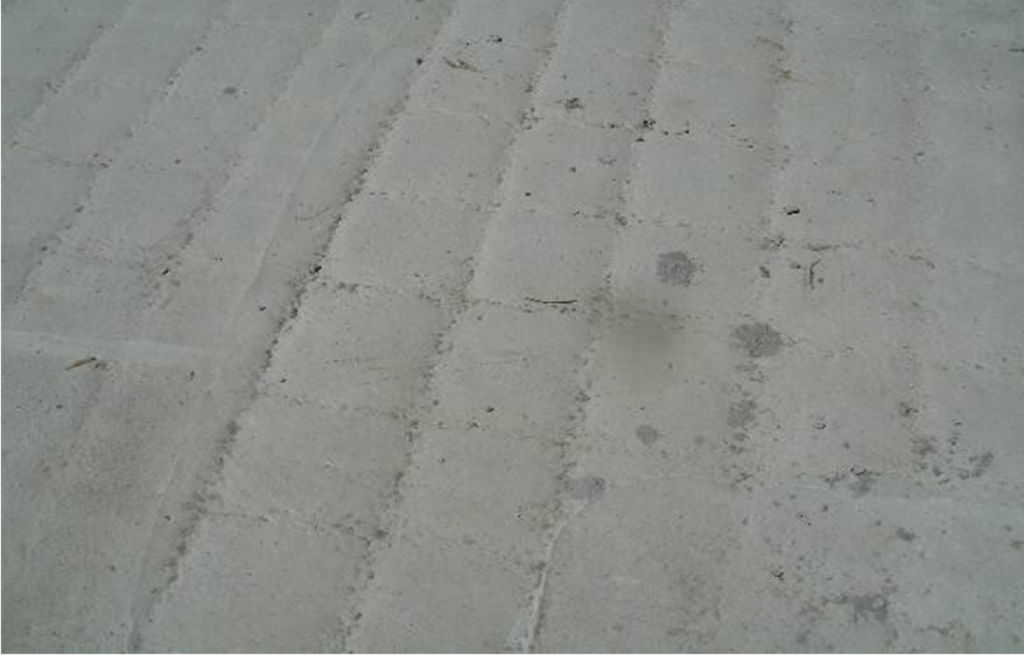
Figure 2 – reinforcement ripple
A phenomenon termed ‘reinforcement ripple’ can occur where the skip-float action over the surface moves the mortar and coarse aggregate away from above the reinforcing bar. This can fail to return fully causing a slight depression to form over the reinforcing bar position and a slightly raised profile between the bars.
Reinforcement ripple will not normally have a detrimental effect on the installation of waterproofing system, but additional thickness of material will be required to fill the depressions.
Curing
The rate at which concrete dries will depend on a number of factors but is mainly affected by climatic conditions and the water/cement ratio of the mix.
Normal weight concrete typically retains 5% moisture when fully cured and because lightweight concrete aggregates are pre-wetted prior to manufacture, their retained moisture content will tend to be higher, but may result in an extended drying time.
It is recommended an in-situ concrete deck is allowed to cure to ensure the concrete has achieved its structural design strength, usually 28 days, and prior to installing the waterproofing system.
Hardness: the surface compressive strength of cementitious substrates after preparation must be excess of 25N/mm² when tested with a rebound hammer.
Cohesive strength: the cohesive strength of the concrete when subject to adhesion tests must be excess of 1.5N/mm².
However, with the agreement of the Principal Contractor, the installation of the waterproofing system can commence earlier subject to a visual inspection and successful adhesion tests witnessed by IKO.
Surface defects
The main causes of a failed Peel test are the presence of surface laitance (a thin layer of residue left after water evaporation) or dusting of the concrete surface.
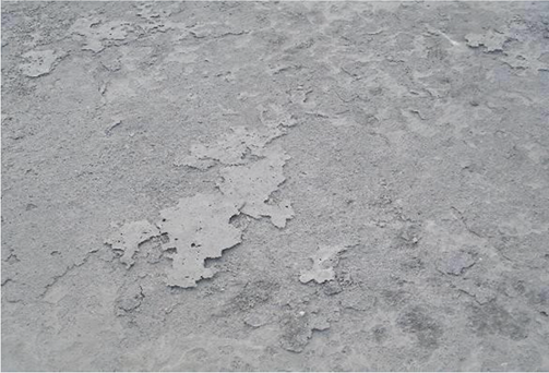
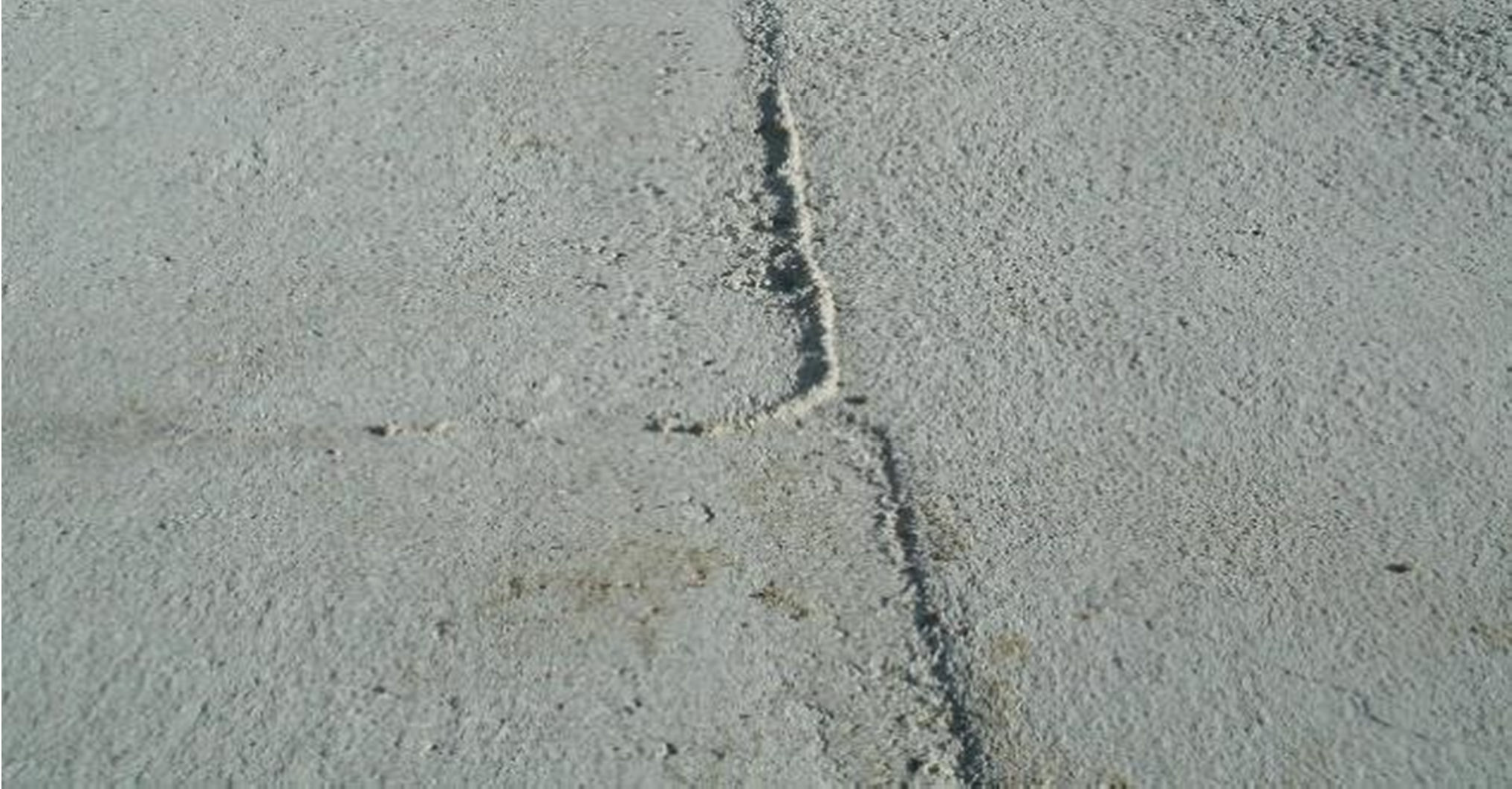
Figure 3 – example of surface laitance
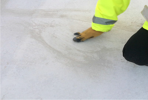
Figure 4 – surface dusting
There are a number of potential causes:
- Premature surface moisture loss – this can occur particularly in summer months if the surface is allowed to dry out before sufficient hydration of the cement has taken.
- Excessive Bleed Water affecting the Water/Cement ratio at the surface.
- Frost shortly following placement which will affect the surface paste integrity.
- Rain shortly after placement – similar affect to excessive bleed water affecting the water/cement ratio at the surface. Usually noticeable within the finished surface.
Curing techniques can also affect the bond of the waterproofing system and procedures involving spray- on waxes should be avoided or if used will need to be removed prior to application.
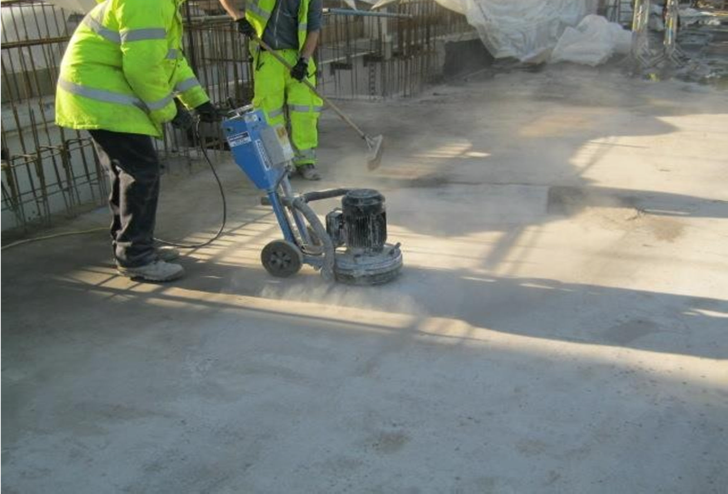
Laitance, dusting and curing materials are usually restricted to the surface only but will need to be removed in order for the waterproofing system to achieve a suitable bond. Light mechanical brushing will normally be sufficient to prepare the surface. However, in more severe cases, shot blasting or scabbling will be required.
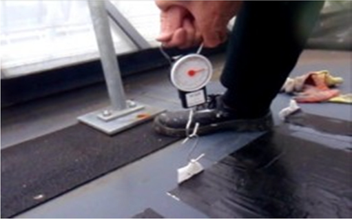
Adhesion test
The type of test we recommend is to apply the specified primer, if required, and when sufficiently cured to apply a 300mm x 300mm test area utilising a 100mm strip of the bituminous vapour control layer membrane.
After curing the strip is connected to a simple luggage weighing scale.
The carrier strip should then be pulled at 90° to the substrate, noting the force reading on the scale. It is important to note where the strip becomes detached known as the “mode of failure”.
This might be at the substrate which may delaminate. Providing the force is greater than 3.5Kg then this is adequate for the minimum recommended adhesion required.
Another method more frequently used is by using a sharp knife, cut through to the substrate making two cuts in the shape of a “V”. The point of the V should then be peeled back. If no coating is removed or split cohesively, leaving a layer of coating on the surface, then the adhesion could be considered suitable.
Pullout tests
When installing mechanically fastened insulation boards or membrane pullout tests must be undertaken to verify that the fastener design load is achieved. Pullout tests should be carried out by an IKO field engineer or by the approved IKOfix supply partner.
A minimum of 6 pullout tests should be carried out for roofs up to 1000m2 and a further 6 for every 1000m2 of roof area thereafter in accordance with ETAG006.
The results of the pullout tests will be checked by IKO Polymeric Technical Services Department and any necessary changes to the fixing layout can be made accordingly.
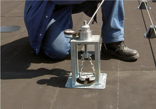
Figure 5 – pullout test
Drainage falls
In order to ensure that a concrete finish complies with the requirements of BS 6229 (Code of Practice for Flat Roofs with continuously supported flexible waterproof coverings), allowance must be made in the design and construction of the structural deck for deflection and construction tolerances.
The recommended minimum design falls should be 1:40 to achieve 1:80 and falls should be sufficient to allow free flow of water to the rainwater outlets.
If you have any queries, please contact our Technical Services Team.
Tel: 01247 488 012
Email: polymeric.technical.uk@iko.com